THIS SITE

Here is a turbine engineer web site.

While dealing with the Cocohouse web site I built a bit of web design skills.

Internet is a great thing that made our world smaller and all the human kind closer to each other.  As turbine people around the world are also some kind of humans the internet made us closer either. 🙂

Hence I decided to put online some of my turbine  and control expertise gained through a lifetime of hands-on experience in the power engineering.  It is to be used by turbine engineers or anybody who wants to become one.

This site contains some of my papers and applications that are available for your non-commercial use.  The applications are listed and briefly explained below:

  • Steam Turbine Thermodynamic
    A simplified core steam turbine design.  The calculus is based on input steam parameters and design conditions.  It predicts the design operating point and the expected output. It also calculates any off- design operating point and predicted output in a case of inlet pressure deviates from the rated one. This kind of assessment is particularly required in geothermal engineering world.
  • ThreeP (bang-bang)
    A time simulation with a bang-bang loop controlling the water level in a vessel.  Was taught this type of bang-bang loop by my teacher prof Sherman back than at the university.  Believe it is quite superior to whatever I’ve seen around since. This application allows you to tune the whole thing, play with it and understand how ThreeP works.
  • TMC Playground
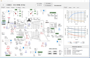
    TMC stands for Turbo Machinery Controls.  This application demonstrate some basic TMC features. It simulates two turbo-generators that can operate in all kind of real life scenarios.  Also demonstrates some advanced load sharing features that I developed through the years of dealing with the matter. Its User Manuals explain well how to go around the playground.
  • Synch Playground
    This application simulates synchronizing generator to grid in a manual mode as it ones used to be.  These days AutoSynch unit does it all by itself.  The simulation gives operators and engineers idea of what is actually happening during synchronizing process. It has its User’s Manual as well.
  • Turbine Dynamic Simulators
    Stand alone C# developed software package that mimic dynamic behavior of various turbo-machines. It creates reliable and robust closed loop environment that can be integrated in all kind of applications.

There is also a part here called Linear Control Theory. That part was put together by prof. Šerman with me just shaping it up for the web publishing. Had a privilege to be prof. Šerman university student and later on worked together through some tough projects.

Originally we had a commenting option enabled for this site. However, spammers were keep flooding us with things so the comments are disabled for now.  If you have any comment or question regarding the contents here please forward it to perica.skoric@arirang.hr


PLCScope

PLCScope is made to assist user in analyzing and troubleshooting PLC controls systems.  It is particularly helpful with demanding controls that operate complex and fast acting power processes as, steam and gas turbines, compressors, boilers, etc.  It has been field-verified with Siemens S7-1500/S7-300 and AB ControlLogix PLC however, it is designed to work with a wider range of other PLCs.

PLCScope consists of two parts.  One works in PLC itself (PLCScope-PLC) with the other part (PLCScope-PC), being a C# application that works within a PC that is LAN connected to the project PLC.


PLCScope-PLC comes as a set of standalone subroutines to be amended to the rest of the control software.  Its task is to keep sending data to the PC.  The data sent are current values of the control algorithm Analog and Boolean variables.  It is not sending all the variables but only those that are of any interest for monitoring and troubleshooting particular control system.  Those variables need to be specified by user.

The Analogs specified are being sent through as per a specified rate.  The rate can be set from as fast as the each PLC scan to anything slower than that.

All the Booleans specified are sent through at the same scan whenever any of the specified variables changes their state from FALSE to TRUE or opposite..

The PLCScope-PC is keep receiving process data and processing them further.  A part of the processing data is to save them to a fixed memory.  Additionally, various PLCScope tools for either on-line or off-line analysing data are available to user.

Live Watch


Live Watch is an online tool. It is continuously displaying selected signals.


Trender

Trender can be used both online and offline.  It is a complex tool for process data visual presentation and analysing.  The rate for analogs can be set from a single scan slower while booleans are taken at each scan whenever any of the booleans that are specified for trending  has changed its state.

Any .csv form external data can be incorporated together with data taken from the project PLC.

The default sorting form is a regular trend with process date against time however, any of the analog variables can be defined as the x-axis.


Historian

Historian saves project data to a fixed memory.  Analogs are saved at a second pace while every single state change of Booleans are saved as it appears.  The amount of the data saved depends only of the fixed memory size used.

Historian is enabled by default as soon PLCScope is connected to its PLC however, it can be disabled if required.

Saved data can be analyzed using trender or SOE viewer.  Trender can pick both Analogues and Booleans while SOE Viewer analyses Booleans only.


TrogLog  

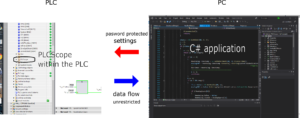
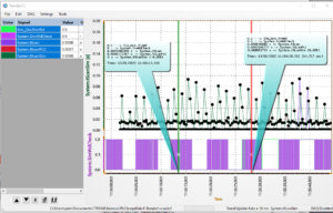
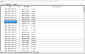
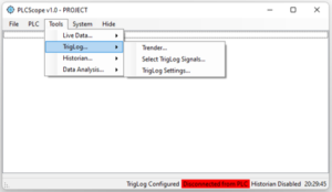
TrigLog continuously monitors specified signals at every PLC scan.  Among the signals specified there needs to be at least one Boolean trigger signal.  The maximum number of triggers is three.  Whenever any of the triggers changed its state all the monitored signals are dumped to a fix memory.

The number of consecutive scans being monitored is 1000 by default however, it can be changed by user. There is also some scans after the trigger saved as well.  The number of scans saved after the trigger  is 50 by default.

The signals saved can be analysed by Trender.


SOE Viewer 


SOE Viewer analyzes Boolean data recorded by Historian.   User can unambiguously determine what is the cause of some process event and what are the consequences.

SOE Viewer can export data as a .csv set to be further analyzed by Excel or else if needed.


If any further interest in PLCScope please drop us an email:
perica.skoric@arirang.hr
office@arirang.hr

Turbine Dynamic Simulators

Turbine Dynamic Simulators are a range of stand alone C# developed software packages that mimics various turbines dynamic behavior at a reasonably high fidelity level.

It models turbine as a lump system utilizing in house developed relatively simple robust and fast numerical methods.

There are two links at the bottom here.  A link to a simulator resembling the core features of an imaginary steam turbine with one controlled extraction. The image bellow that one is a link to a YouTube video that demonstrates some of the simulator features.

Apart from various steam turbines there are also simulators for other turbo-machines that have been mastered.  A core generic versions of gas turbine, water turbine, pump and compressor simulator have also been developed and is available to be tuned to resemble any such machine available at the market.

The simulator creates a reliable closed loop environment that can have all kind of applications.  At present it has been proven as a perfect tool for developing and pre-commissioning PLC turbine control software as well as for operators training.

The simulators are able to communicate to other Win applications, as various PLC emulators or else.  We have already executed projects with the simulator communicating to the PLC emulators namely,  Simatic S7 (a peper here) and AB CompactLogix.  That can be extended to any other PLC having it’s emulator.

Drop me a note for any additional info about this application.

EX1 STEAM TURBINE SIMULATOR
(*.RAR ARCHIEVED *.EXE FILE)


SOME TURBINE CONTROL BASICS

Here are few presentations covering turbine control basics.  They are focused onto the process aspect of the whole turbine control thing.

These days I see sharp young guys with a deep and detail PLC knowledge doing controls.  Sometimes I don’t see the same strength at the process control side.

Such a discrepancy is easily understood as the PLC technology is so easily accessible these days.  Just Google alone can bring you to all the nitty gritties of,  Siemens, Allan Bradley, ABB, Honeywell, and others.

However, it’s much harder to master the process control side.  It gets to you only through years of hands-on dealing with the matter itself.

Hence, here are some basic process control things related to turbine controls. It is put into three presentations already delivered to their targeted audience a year ago.  The feedback was quite positive all together.

The presentation are:

  • TURBINE CONTROLS BASICS;
  • TECHNICAL THERMODYNAMIC
    Selected Fundamentals Related To Steam Turbine Controls;
  • STEAM TURBINE CONTROLS;

Click to cover page link gets you to each of their .pdf versions.


STEAM TURBINE ITCC RETROFIT IN PETROKEMIJA KUTINA

 Introduction

Turbomehanika successfully retrofitted the controls for two identical steam turbine trains that are parts of the Old Nitric Acid plant in Petrokemija Kutina.  The trains are manufactured by Escher Wyss and commissioned back in 1968. Operating continuously since. Each train consists of a steam turbine, two process compressors and a gas expander all coupled together.  The steam turbine being the main drive with the expander supplementing it by expanding the process product gasses through.

The scope of the retrofit was to replace the existing steam turbine control and the compressors antisurge protection with a new PLC based Integrated Turbine Compressor Controls (ITCC) system.  Siemens SIMATIC S7-1500 PLC together with Bently Nevada Adapt 3701/55 ESD are used as the PLC hardware.

Turbomehanika have been the main contractor for the job with Arirang and Intea being subcontractors.

The Old Control System

The old control system consisted of hydraulic turbine controls and compressor antisurge protection. They were both using the same 7barg hydraulic/lube oil system.

Steam Turbine Controls had a flywheel isochronous governor operating three steam control valves actuated by a linear hydraulic servomotor.  The governor and the trip unit were both integrated together at the steam turbine front pedestrian.  The project spec required to use the existing trip device.  Separating one from each other was quite a challenging task that required gaining a deep knowledge of the Escher Wyss control concept. The governor was cut out while the trip device and the servomotor remained a part of the current system.


Compressor Antisurge System had a control unit and the blow-off valve operated by a hydraulic servomotor.  The control unit was cut out while the blow-off valve with its servomotor remained parts of the current ITCC.

All through the recent years the customer were keep experiencing issues with the antisurge controls.  It would open the blow-off valve when it was not supposed to causing costly plant shutdowns.  While commissioning the new controls we found that in some operating modes compressors are expected to run quite near to the surge region. The old antisurge controls were most probably not being able to deal with that operating situation.

Continue reading “STEAM TURBINE ITCC RETROFIT IN PETROKEMIJA KUTINA”

THE TURBINE BOOK

Kostjuh-Frolov

A.Kostyuk and V.Frolov, STEAM AND GAS TURBINES

At university they taught us the turbine theory and practice using this book.

It was also used as guidance to my older colleagues when they were establishing  Jugoturbina turbine design practice.

This is “the” book for learning turbines if you are limited to the English language as myself.

The steam turbine section has a lot of details, numbers, examples.  Following those you would be able design a turbine for real.

The gas turbine section presents you with the basics that can be easily extrapolated to wherever are your needs.

Drop mi a line if you are interested in *.pdf

GEOTHERMAL INTEGRATED CONTROL

I haven’t been involved with geothermal power field since year 2000.

Here is what we did for the Wayang Windu project in Indonesia.

Geotherml paper

At the time Fuji Electric installed there the largest geothermal steam turbine ever, though it might not be the largest any more.

We implemented a concept not previously used in geothermal plant control.  Used “turbine follow” approach, used normally in conventional and nuclear plants.  Worked well at the end.

Like all new ideas it was not accepted without some resistance.

I gave the technology and supervised the engineering. however, there were many others pushing it through. Some of them are in the paper authors list.

In the meantime Fuji Electric installed another unit there.  Guess they extended the integrated concept further.  Would like to hear from my Fuji Electric friends how that all went through.


HOW FAST NEEDS TO BE TURBINE PLC GOVERNOR?

( A STUDY BASED ON TURBINE OVERSPEED PROTECTION )

INTRODUCTION

Virtually all turbines are required to operate either at a fixed speed or over a range of fix speeds. Operating speed can range from less than 100 RPM for low head hydro turbines to up to 500,000 RPM for some micro gas turbines. The operating speed is held constant by ensuring that the input power matches the power needed by the driven machine. That balance is maintained by control system usually called the “governor”.

Relying on the governor only is not sufficient to guarantee safe turbine operation. Since the early turbine designs there have always been two independent systems responsible for keeping turbine within the safe operating speed range, they are governor and overspeed protection.

The first governors and overspeed units were mechanical devices. Further on hydraulics took over,  later on to be replaced by analog electronic.  However, these days governors and overspeed units are normally PLC devices driven by a specially designed software.

Since PLC took over turbine control there is always a discussion on how fast the PLC needs to be to do the job.

This paper is dealing with the same issue. It is trying to quantify overspeed protection requirements for prompt reaction. It is done by combining real world data with dynamic modelling and simulating.
Continue reading “HOW FAST NEEDS TO BE TURBINE PLC GOVERNOR?”