
TMC playground demonstrates Turbo Machinery Controls basic features. It does so by simulating a set of two turbo-generators that can operate either islanded or in parallel with the public grid.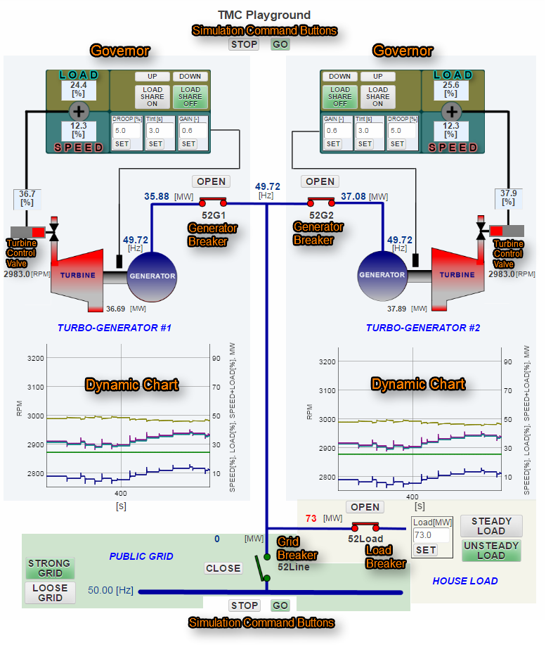
Each turbine drives 50Hz synchronous generator of 100MW output. Only real power and frequency are being simulated as far electrical parameters are concerned.
Turbines are controlled by their Governors. The governors operate the Turbine Control Valves. Each turbo set has some small mechanical losses simulated.
The TMC playground simulates steam turbines controls however, the same control philosophy applies for any other prime mover driving electric generator as, gas turbine, diesel engine, hydro turbine, wind turbine, etc.
This page explains TMC playground basic features. Additionally there is Exercise page with few labs that are proving some major TMC points.
Generator Breaker
Each generator has its Generator Breaker, 52G1 and 52G2 respectively. When the generator breakers are opened the units run at Full Speed No Load (FSNL). As only the real power is being simulated any precise synchronizing has been omitted. If both generator breakers are closed the turbo sets operate together in parallel.
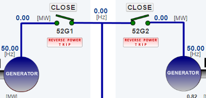
The breakers have a rudimentary reverse power protection. It trips the unit breaker in case electric power starts to “flow” towards the unit generator. A red alarm tag “REVERSE POWER TRIP” is displayed when the breaker is tripped by the protection. The alarm is cancelled ones the breaker closes again.
Dynamic Chart
Each turbo set has its own Dynamic Chart. It follows the major control variables as speed [RPM], governor output SPEED [%], governor output LOAD [%], SPEED + LOAD (Control Valve Opening) [%], Unit Output [MW].
Simulation Control Buttons
There are two sets of Simulation Control Buttons. STOP button friezes the simulation at any time. The freeze mode is useful to analyze quick control events. Button GO resumes the simulation.
House Load
House Load section has four elements. 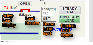 They are:
- Active Load Display,
- Load Breaker (52Load),
- House Load Input
- Random Load Option.
While Load Breaker is open Active Load Display displays the set load in gray color. Ones 52Load is closed the display goes red. House Load Input sets a step change. It takes inputs between 0MW and 200MW. Random Load Option introduces random load changes ones UNSTEADY LOAD button is clicked. Both the steps and the periods between the steps are randomised. When STEADY LOAD button is selected it clears the random steps and fixes the load to the set value.
Public Grid
Public Grid section consists of five elements. 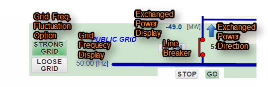 They are:
- Grid Freq. Fluctuation Option,
- Grid Frequency Display,
- Line Breaker (52Line),
- Exchanged Power Display,
- Exchanged Power Direction.
Line Breaker connects both the generators and the house load to the grid. At soon as 52Line closes the grid frequency becomes the synchronous frequency for the whole system. Exchanged Power Display shows the amount of power being exchanged with the grid. In a case the power “flows” to the grid the sign is positive. In a case the “flows” goes from the grid to the system the power is negative. Additionally there is also Exchange Power Direction arrow that visually shows the power direction. Grid Freq. Fluctuation Option introduces slight grid frequency fluctuation around 50.00Hz. Those fluctuations are normally present with public grids that are not well balanced and dispatched.
Governor
 Governor is the key element of any TMC System. This governor has two main functions. They are SPEED control and LOAD control. The outputs of these two function added together make Turbine Control Valve demand. SPEED control is a PI loop that is droopped. The drooping transforms a Proportional-Integral (PI) speed control into a steady state Proportional (P) control. P control (contrary to PI) allows an increase of the control error. The increase is just proportional with the speed control output. P control characteristic is essential for any governor to achieve stable operation in parallel mode (Lab 1.).
The PI part is calculated by a Velocity PI algorithm developed for this particular application.
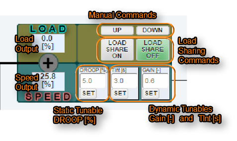
Tunables GAIN [-] and TInt [s] are responsible for SPEED control dynamic behavior as, prompt reaction, dynamic stability, etc. Tunable DROOP [%] is responsible for the static error.
Field Speed Output displays the output of SPEED control function.
LOAD control has Manual Commands. Clicks on buttons UP and DOWN move the unit output up and down respectively. For continues UP and DOWN the buttons need keep clicking.
Compared to other commercial governors this governor has a unique capability. It can automatically share load between units. No additional load sharing device is required. Load Sharing Commands become available as soon both units are paralleled and isolated from the public grid. (Lab 2.). Ones Load Sharing is active the units keep 50Hz together by sharing load in a preset manner.
Field Load Output displays the output of LOAD control function.