nserman@fsb.hr Transfer Function Concept Digest
11. BASICS OF CLOSED LOOP DYNAMICS QUALITATIVE ANALYSIS
Closed-loop dynamics is optimized to achieve the closed-loop stability with a satisfactory transients damping and a transients duration to be as short as possible. In terms of the Bode diagram stability margins this means that the stability margins should be:
- positive (provides stability as such),
- sufficiently large (provides adequate transients damping),
- within relevant frequency range (provides faster transients vanishing).
To comply with #3 the shaded area in fig. 11.1 should be as far as its achievable to the right side.
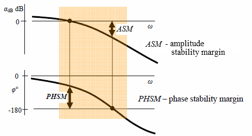
Figure 11.1 Stability margins and relevant frequency range (shaded area) in an open-loop frequency characteristics Bode plot.
Frequency characteristics of a serial connection in Bode diagram are made by a simple summation of the respective block characteristics. This offers a rational ground for qualitatively analyzing of what are the effects of additional block inclusion into the open loop.
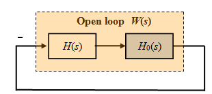
Figure 11.2 Closed-loop system under consideration – open loop W(s) = H(s) H0(s) encircled by negative unity feed-back
Transfer function H(s) in fig 11.2 is an additional block. Fig 11.3 shows what would be the effects if that block is a static gain while fig 11.4 shows the same in a case of an integrator.
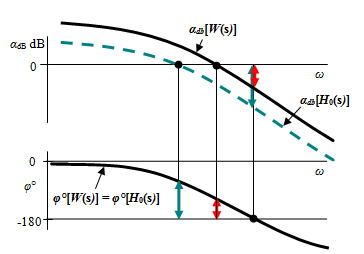
Figure 11.3 Effect of adding static gain H(s) = K to the component H0(s) when K > 1.
Adding a static gain to the existing component H0(s) results in an amplitude frequency characteristic vertical translation. The transition is upwards for K > 1 and downwards for K < 1, thus directly influencing the stability margins. The red arrows are the stability margins after the inclusion of H(s).
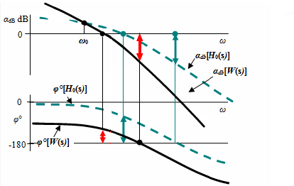
Figure 11.4 Adding of an integrator s ![]() to the existing component H0(s)
to the existing component H0(s)
Adding an integrator to the existing component H0(s) rotates the amplitude frequency characteristic around its point at frequency ω0. The phase characteristic is shifted 90° downwards.